- 您现在的位置:买卖IC网 > Sheet目录362799 > EV3205DJ-00A (Monolithic Power Systems, Inc.) 1.3MHz Fixed Frequency 5 White LED Driver
MP3205 – 1.3 MHz FIXED FREQUENCY 5 WHITE LED DRIVER
MP3205 Rev. 1.3
7/13/2005
www.MonolithicPower.com
4
MPS Proprietary Information. Unauthorized Photocopy and Duplication Prohibited.
2005 MPS. All Rights Reserved.
TM
APPLICATION INFORMATION
OFF ON
MP3205
V
IN
2.5V to 6V
LED1
LED2
LED3
MP3205_F02_AP_S01
CMDSH-3
IN
EN
GND
4
2
FB
3
SW
5
1
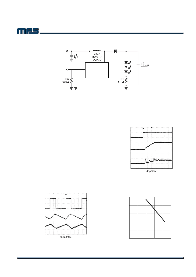
Figure 2—Driving 3 White LEDs
COMPONENT SELECTION
A typical application circuit can be seen in Figure
2. The 3 white LEDs can be driven from a voltage
supply range of 2.5V to 6V at an output current of
20mA. A 0.22μF output capacitor is sufficient for
most applications but an output capacitor up to
1
μ
F may be used. A 22μH inductor with low DCR
(Inductor resistance) is recommended to improve
efficiency.
A
1μF
ceramic
recommended for the input capacitance in the
real system. Schottky diodes have fast recovery
and a low forward voltage and are recommended.
capacitor
is
Schottky diodes rated with 100mA to 200mA
are sufficient for the MP3205. The switching
characteristics during normal operation can be
seen in Figure 3. The MP3205 has internal
soft-start to limit the amount of current through
V
IN
at startup and to also limit the amount of
overshoot on the output. The current limit is
increased by a fourth every 40μs giving a total
soft-start time of 120μs.
V
OUT
RIPPLE
(AC COUPLED)
50mV/div.
V
SW
5V/div.
I
L
100mA/div.
MP3205_F03_WF01
Figure 3—Steady-State Operation
V
IN
=3.6V, 3 LEDs, 20mA
Figure 4 shows the startup behavior of the
MP3205. The ramped voltage that is added to the
current sense amplifier reduces the current output
as the duty cycle increases. As more LEDs are
added, the output voltage rises but the current that
can be delivered to the load is reduced as well.
V
OUT
5V/div.
V
EN
5V/div.
I
IN
100mA/div.
MP3205_F04_WF02
Figure 4—Startup Waveforms
V
IN
=3.6V, 3 LEDs, 20mA
Figure 5 shows the dependence on current limit
versus duty cycle.
500
400
300
200
100
0
C
0
20
40
60
80
100
DUTY CYCLE (%)
MP3205_F05
Figure 5—Current Limit vs. Duty Cycle
发布紧急采购,3分钟左右您将得到回复。
相关PDF资料
EV3213DH-00A
700KHz/1.3MHz Boost Converter with a 3.5A Switch
EV4101
32-bit Microprocessor that Executes MIPS I,a Subset of MIPS II,and a Subset of the MIPS16 Instructions.(32位微处理器(执行MIPS I,MIPS II的子集,MIPS16的子集指令))
EV5103
G5103 White LED Demo Board V1.0
EV5103-10
G5103 White LED Demo Board V1.0
EV6001DN-00A
Monolithic Flyback/Forward DC-DC Converter Evaluation Board
EV6001DN-00D
WLED Driver Evaluation Board
EV7720DS-7782-00D
150W Class D 5.1 Channel Audio Board
EV7722DF-00C
20W Stereo Class D Single Ended Audio Amplifier
相关代理商/技术参数
EV3212X05XA_D5X WAF
制造商:Fairchild Semiconductor Corporation 功能描述:
EV3213DH-00A
制造商:MPS 制造商全称:Monolithic Power Systems 功能描述:700KHz/1.3MHz Boost Converter with a 3.5A Switch
EV322
制造商:FASTRAX 功能描述:KIT EVAL GPS RECEIVER UC322 制造商:FASTRAX 功能描述:UC322, GPS RECEIVER, 20-CHANNEL, EVALUATION BOARD; Silicon Manufacturer:Fastrax; Silicon Core Number:UC322; Kit Application Type:Sensing - Navigation, Position; Application Sub Type:GPS Receiver; MCU Supported Families:SiRFstarIII ;RoHS Compliant: Yes
EV32C1
制造商:ECLIPTEK 制造商全称:Ecliptek Corporation 功能描述:CERAMIC SMD3.3V HCMOS/TTL VCXO
EV32C1A1A1-35.328MTR
制造商:ECLIPTEK 制造商全称:Ecliptek Corporation 功能描述:CERAMIC SMD3.3V HCMOS/TTL VCXO
EV32C1A1A2-35.328MTR
制造商:ECLIPTEK 制造商全称:Ecliptek Corporation 功能描述:CERAMIC SMD3.3V HCMOS/TTL VCXO
EV32C1A1B1-35.328MTR
制造商:ECLIPTEK 制造商全称:Ecliptek Corporation 功能描述:CERAMIC SMD3.3V HCMOS/TTL VCXO
EV32C1A1B2-35.328MTR
制造商:ECLIPTEK 制造商全称:Ecliptek Corporation 功能描述:CERAMIC SMD3.3V HCMOS/TTL VCXO